Recently I was contacted by an old friend whose modern, high-efficiency woodstove has given him no end of problems. Apparently (see HVAC-Talk and Hearth.com threads to this effect) this is a well known issue on the Quadra-Fire Mt Vernon pellet stove that uses this Bergquist 450-15-0031 control board. He has had regular issues with the control board reporting a motor jam, and previously was able to reseat the connector for one of the motors to (usually) get it working again. However, after years of doing this, the connector lost contact pressure and eventually charred one pin badly enough that it no longer functioned at all. He asked me if I was willing to take a shot at repairing it, as I have 25 years experience in electronics board level work.
Upon receiving the board, I noted that the connector was in fact charred. I was able to locate the correct components for a repair and perform the repair. Here are the parts you will need if your combustion motor connector at the board is burned up:The original header and replacement, and the board cleaned up:
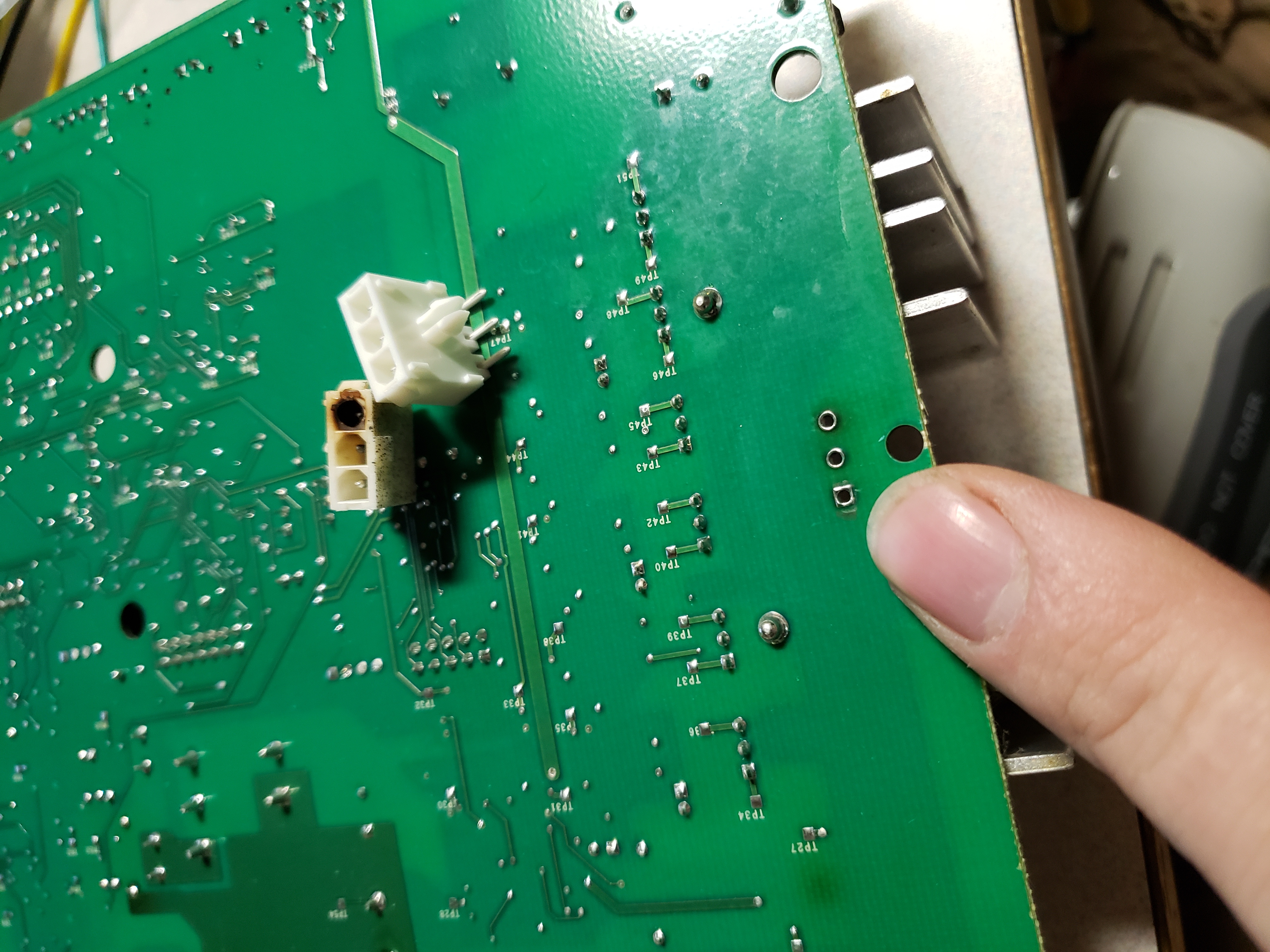
The new header installed:

Note - this burn mark between TP27 and TP29 probably indicates a future failure point on some control boards, but it was not yet failing on this one. This is
under one of the 3
parallel SMT shunt resistors used to monitor convection blower 3 phase H-bridge current draw. One of the resistors has created a hotspot due to incorrect board
design leading to it seeing more current than the other two. I will be watching for this to cause issues on other boards in the future.

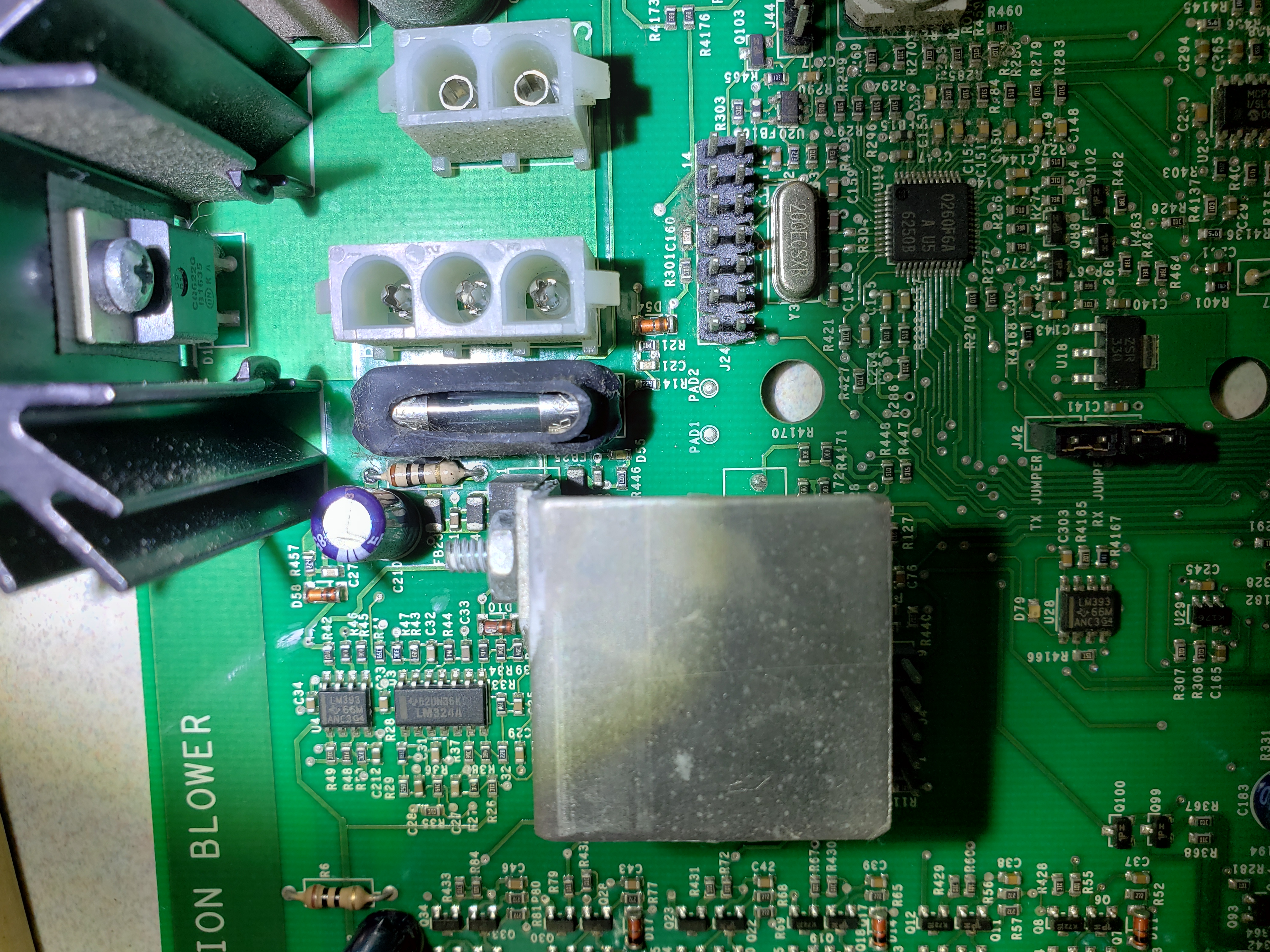
R355, damaged by heat. This 10 ohm, 1/4 watt resistor is in the input filtering to the LM340 +5.0 voltage regulator (U1) mounted to the L shaped heatsink
just left and down from it. I am not sure why they chose such a small wattage or placed it so close to the board, but it was badly burned on this unit.
While it has not yet failed, it was going to soon. I would strongly recommend upgrading this resistor to a 1/2 or 1 watt unit and crimping the leads to
allow at least a 1/2 inch standoff from the board for cooling and to limit thermal damage to the PCB substrate.

R355, replaced. Note the discoloration of the PCB substrate. This is why the replacement should be a higher wattage.

R355, replaced, top. In this case a factory equivalent was installed. My personal recommendation is again to upgrade to a higher wattage, but this is up
to you.
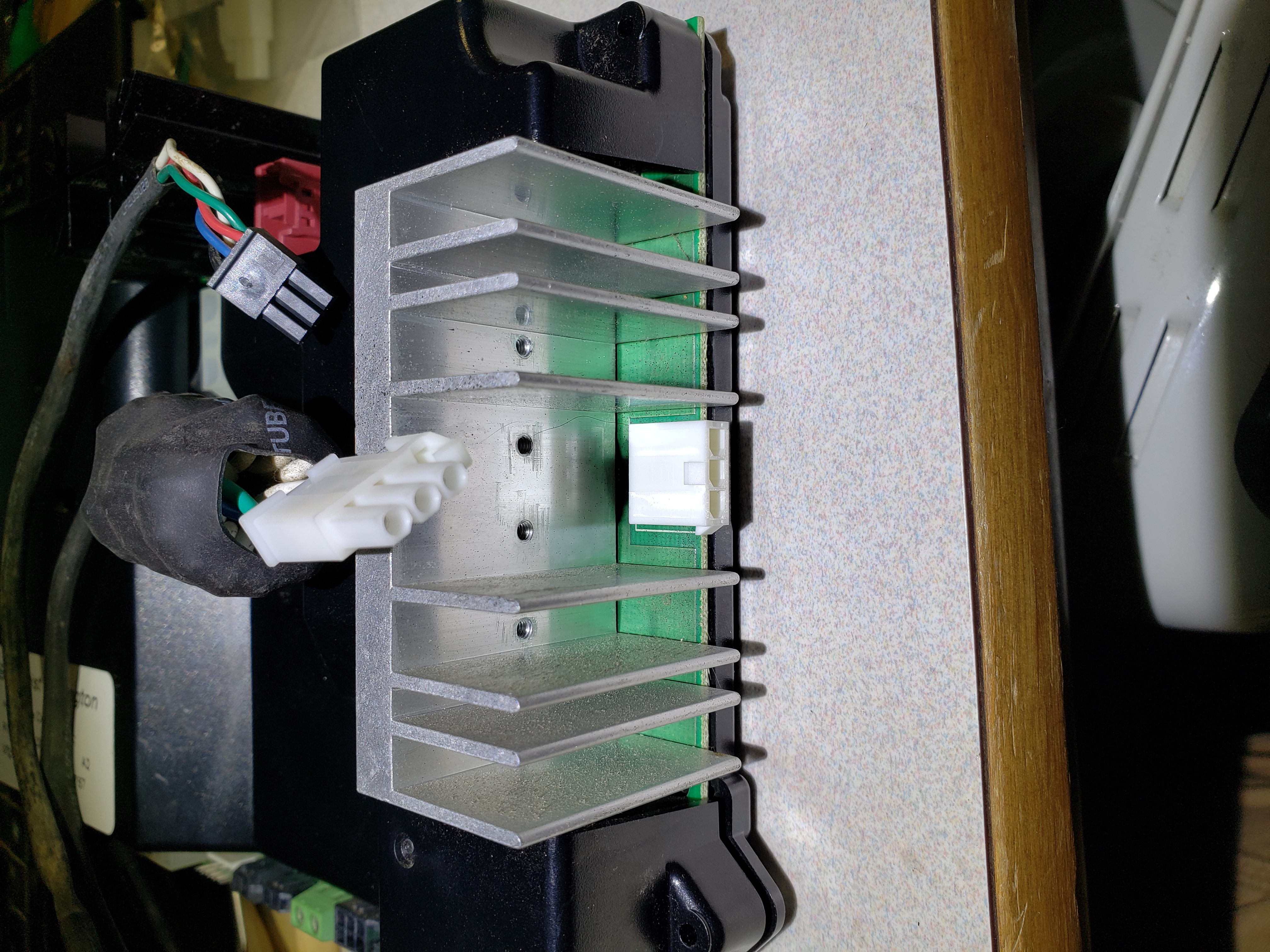
The original convection motor harness plug:

Repair completed:
This information is presented for your enlightenment only. It is NOT a guide for the laymans repair of this unit, and only skilled and properly licensed individuals should employ this information where life and limb is at risk. If you are not 100% certain of your ability to repair a 4 layer PCB that operates a solid fuel combustion furnace in your house or place of business, you SHOULD NOT take on this project. This disclaimer is for my legal defense; any risks associated with performing the repairs pictured here are yours and yours alone. If this repair is not performed by appropriately skilled individuals and using the correct tools and materials, your insurance company may well drop you if your work results in a fire. Under no circumstances shall I be responsible for this. Every attempt has been made to accurately describe the process here, but there is a reason this should only be attempted by properly skilled and licensed individuals - if I missed something in writing this down, it is on you to find my mistake and not follow in my footsteps. Because I am NOT licensed as an electronics repair technician trainer nor is this equal to the original manufacturers training materials. My liability for your use, misuse, or disuse of this information is limited to exactly what you paid for it - zero dollars. The stakes are high on this repair, as this equipment is quite literally intended to set things on fire inside of your house. If you repair it improperly, it may set the wrong things on fire, or apply more fire than you may prefer, or less. The unit it is installed in is well known for being a flawed design at this point in time, and if it failing while you are away could result in frozen pipes and property damage, it is strongly recommended to have a backup source of heat in place.